PCM Flash dump, Part 1
Step 1: install jumpers
The 2 CPU signals *IPIPE/DSO and
*IFETCH/DSI are not used during normal CPU operation. During prototyping
these 2 component pads would have 0 ohm resistors populated in order to connect
these 2 signals to the 90 pin diagnostic connector. For production they
are not fitted. Photo 1 shows the location of these jumpers on PCM service
number 16207326. The traces that connect them to the CPU are highlighted
in blue, you should be able to follow the traces to the proper location on your
PCM should it be different. Figure 1 shows that these 2 pins are in fact
*IPIPE/DSO and *IFETCH/DSI.
- If your CPU has a conformal coating (thin coat of silicone over
everything) then scrape it off before soldering. Your fingernail will
work fine. My PCM had this, but some don't.
- Attach the wires as shown.
Alternative: The BDM wires
for these 2 signals may be attached to the vias immediately above the jumpers,
marked in yellow. In this case the jumpers do not need to be installed.

Photo 1 --
Location of jumpers, vias, and traces for BDM signals *IPIPE/DSO and
*IFETCH/DSI
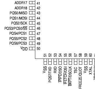
Figure 1 --
Pinout of Southwest corner of 68332
Step 2: Attach BDM connector
You will need a 5x2 piece of
male header, and some wire-wrap wire to make the connector. Use a
different color for each signal if possible. First attach the wires to the
header strip per Motorola's recommended connection (see Figure 2). Leave
the wires plenty long to wrap around to the other PCB. Figure 2 is the top
view, and will be reversed when you are looking at the connector from the bottom
soldering wires to it.
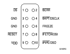
Figure 2 -- Recommended pinout for BDM connector
Once the wires are attached properly, attach the connector to the blue knock
sensor module connector using a hot glue gun. Use a nice large booger of
hot glue, it'll make the soldered connections more reliable. If this is
done correctly it won't interfere with the fit of the knock sensor module.
See photo 2. Remember to mark which end of the connector has pin 1.
I used a red marker on the end of the knock sensor module connector.
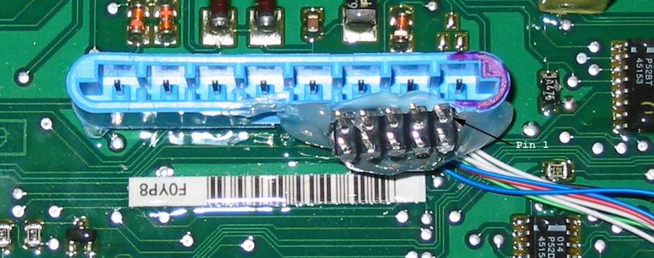
Photo 2 -- hot
glue the BDM connector to the knock sensor module connector.
Step 3: Attach the BDM wires
The signals needed for the BDM
are all available on the 90 pin diagnostic connector, as shown in photo 3.
This connector pinout is common to 32 bit PCMs, so this step shouldn't vary by
PCM service number. The location and names of the signals are annotated on
photo 3, and are also in table 1. The rows are labelled X,Y,Z, starting at
the top, and numbered 1-30 starting at the left. Scrape off the conformal
coating if present, cut the wires to length before attaching them, and when
they're all done apply a dab of hot glue to each one.
Alternative: The wires for *IFETCH/DSI and *IPIPE/DSO may be
attached as described in Step 1, in which case they won't be attached as in
Photo 3, and the jumpers from Step 1 won't be installed.
| BDM connector pin |
diagnostic connector pin |
Signal |
BDM connector pin |
diagnostic connector pin |
Signal |
| 1 |
X7 |
*DS |
2 |
Y12 |
*BERR |
| 3 |
X4 |
GND |
4 |
Z29 |
*BKPT/DSCLK |
| 5 |
X4 |
GND |
6 |
Z30 |
FREEZE |
| 7 |
Z12 |
*RESET |
8 |
X11 |
*IFETCH/DSI |
| 9 |
X25 |
VCC |
10 |
X13 |
*IPIPE/DSO |
Table 1 -- Connecting the BDM wires
to the PCM diagnostic connector.
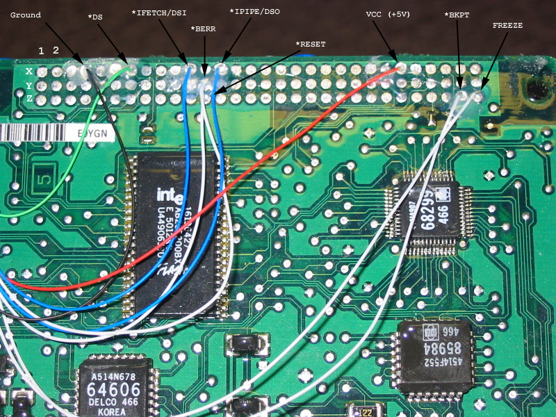
Photo 3 --
Connecting the BDM wires to the PCM diagnostic connector.
Step 4: Check connections
Check continuity from the
diagnostic connector in photo 3, to the BDM connector in photo 2. Make
sure that all the connections are good, no pins are shorted, and that the pins
are in the proper place according to figure 1. Figure 1 is the top view.
Step 5: Power the PCM
This step is only if you'll be using
the PCM on the bench. You'll need a 12 volt power supply, capable of 1 amp
output. I tried a 14v/700mA wall wart and it wasn't up to the task.
Table 2 shows the power connections. For PCM service number 16207326,
connector C1 is the blue one and attaches to the digital PCB (the one with the
68332). Connector C2 is the clear one that attaches to the analog PCB
(with the knock sensor module connector). You'll need a junkyard harness
to power the PCM on the bench. Cut the PCM connectors away from the rest
of the harness.
| PCM connector pin |
color |
function |
Connect to |
| C1-19 |
pink |
ignition feed |
+12 |
| C1-20 |
orange |
battery feed |
+12 |
| C1-21 |
black/white |
PCM ground |
GND |
| C1-56 |
black |
sensor ground |
GND |
| C1-60 |
black/white |
PCM ground |
GND |
| C2-21 |
black/white |
PCM ground |
GND |
| C2-60 |
black/white |
PCM ground |
GND |
Once you're sure that all the connections are correct, power up the
PCM. Check to make sure that you have +5V across pins 9 and 3/5 of the BDM
connector. Once that checks out you're ready for part 2: BDM
hardware and software. Reassemble the computer, and remove the knock
sensor module cover in order to access the BDM connector (see photo 4).
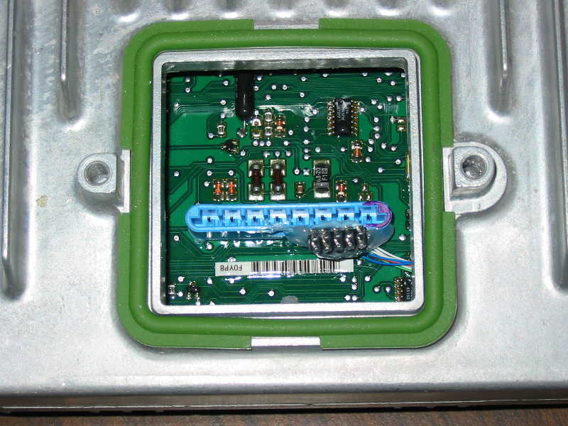
Photo 4 --
Accessing the BDM connector when the computer is assembled.