Beyond the Basics
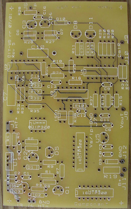
This image is handy to have around during assembly, since labels are often
hidden under the parts once they're installed.
Parts Kit (includes resistors, capacitors,
diodes, transistors, and more)
Resistors
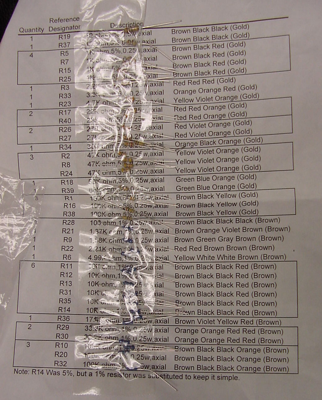 Organization
like this makes assembly much easier. A color code may have been mislabelled
on some early kits, but the resistor is in the right spot and you should
use the DVM to verify those horribly colored bands on the blue resistors
anyway.
Organization
like this makes assembly much easier. A color code may have been mislabelled
on some early kits, but the resistor is in the right spot and you should
use the DVM to verify those horribly colored bands on the blue resistors
anyway.
Caps, Diodes, Chips, various bits
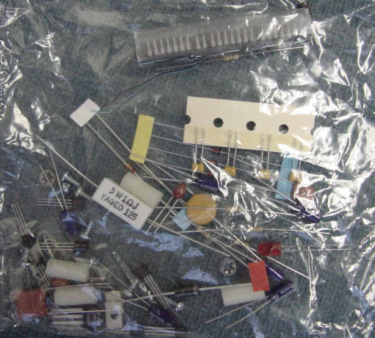 You'll
want to make a sheet similar to the one above for
this bag of parts. More in the identification section of this document.
Don't try to show how savvy you are by assembling parts right out of this
bag.
You'll
want to make a sheet similar to the one above for
this bag of parts. More in the identification section of this document.
Don't try to show how savvy you are by assembling parts right out of this
bag.
Sensor
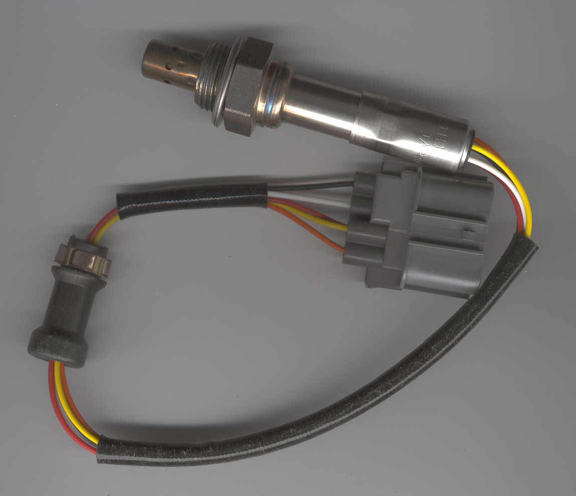 92-95
Honda Civic, 1.5L VTEC 5 wire
92-95
Honda Civic, 1.5L VTEC 5 wire
Part Nos
36531-P07-003
Ekland OS791
Bosch # 13 246
Wells # SU4395
The Parts Bin part #: C5010-75044
NOTICE: This sensor is apparently on backorder from all common vendors. The sensor
sold for around $120 in January 2002 from www.thepartsbin.com. This was apparently a cut rate price, since the more common venues with local brick-n-mortar stores like NAPA, AutoZone, and CarQuest carry the part in the $150 range. Backorders were the word of the day in Feb 2003. The online Honda parts store www.hparts.com apparently sells the sensor for $250. Honda dealerships and import repair shops claim to have them available for around $350. It is unknown whether these latter vendors' units are on backorder or not.
Connector
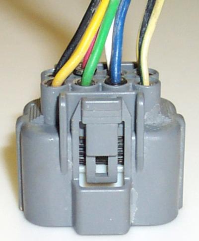 Mating connector for O2 Sensor. (photo by Bryan Zublin)
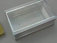
Enclosure
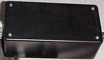 Radio Shack has several project box choices or you can re-use other hardware.
Wires
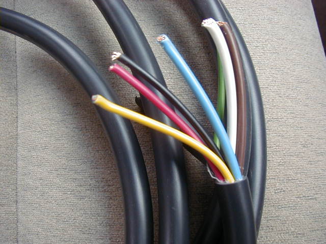 Power for the unit needs to be reliable (ie resist the urge to use a cigarette lighter plug) and fused (3 amp). Wiring to the sensor needs 7 conductors, 2 of which should be at least 18 gauge (to carry the high currents for the sensor heater).
Mounting Hardware
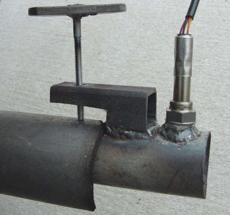
While it is possible to temporarily replace the OEM sensor (and render it useless), a better
solution is something which can be attached to the tailpipe. This will only work if the vehicle does NOT have a functional catalytic convertor, and only if the exhaust system is short enough not to cool the sensor back to "warmup" mode. The best solution would be to tap into the exhaust reasonably close to the engine and add an extra bung (thanks to Joel LaBenz for the step-by-step on his installation. The strange formatting is my fault, btw! It's on the todo list.). O2 sensor bungs are available from speed shops, or can be made by cutting an "anti-fouler" spark plug adapter in half. Be sure to remove the WB sensor when not in use! As Joel points out, an 18mm oil drain plug (again availabe at the HELP! display) should make a nice plug.
Soldering Tools
 Doesn't
get much cheaper than this. Radio Shack supplied the soldering iron stand,
the rosin core solder, heat sink pliers, and the solder sucker. The 30
watt iron is fine for small electronics. Save your large "gun" type iron
for soldering 18ga wires, if you feel the need. The stand helps prevent
burns on the table. Always use a rosin core solder for electronics. The
heat sink pliers should be clipped onto delicate component leads (like
transistors) while soldering to prevent overheating and are also great
for bending component leads.
Doesn't
get much cheaper than this. Radio Shack supplied the soldering iron stand,
the rosin core solder, heat sink pliers, and the solder sucker. The 30
watt iron is fine for small electronics. Save your large "gun" type iron
for soldering 18ga wires, if you feel the need. The stand helps prevent
burns on the table. Always use a rosin core solder for electronics. The
heat sink pliers should be clipped onto delicate component leads (like
transistors) while soldering to prevent overheating and are also great
for bending component leads.
Other Tools
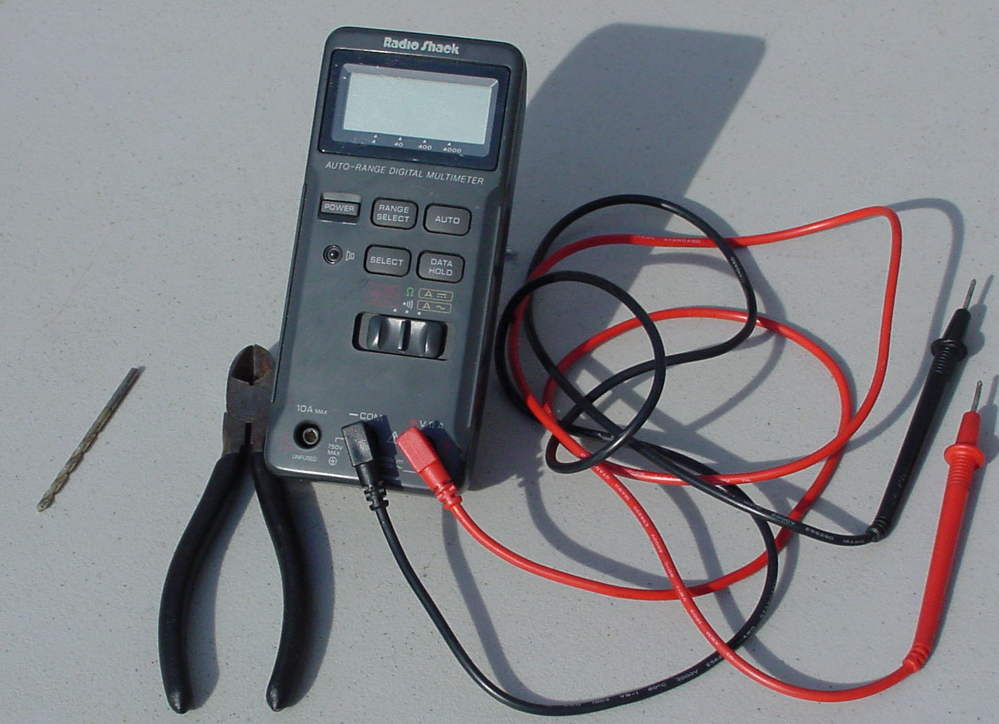 A
1/8" (or slightly smaller) drill bit, cutting pliers, and a Digital Voltmeter.
Better voltmeters have a higher internal resistance. The one pictured is
mid- to low end. A $5 version would work equally as well for building the
DIY-WB, but it's nice to have a decent DVM around. If used to read the
output of the DIY-WB, it'd be silly to settle for the $5 meter here.
A
1/8" (or slightly smaller) drill bit, cutting pliers, and a Digital Voltmeter.
Better voltmeters have a higher internal resistance. The one pictured is
mid- to low end. A $5 version would work equally as well for building the
DIY-WB, but it's nice to have a decent DVM around. If used to read the
output of the DIY-WB, it'd be silly to settle for the $5 meter here.
Diodes (of the two lead variety)(PLEASE REVIEW-Udated 07/19/2002)
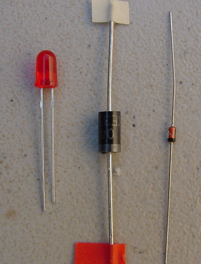 D2
LED, D3 1.5KE-33A, D4 1N4746A 18v 1w.
D2
LED, D3 1.5KE-33A, D4 1N4746A 18v 1w.
The cathode (-) is identified as the end having the stripe , or a "-" marking.
On the schematic, the anode is the base of the triangle and the cathode is the straight bar with
the triangle pointing at it. Notice that the cathode (-) being identified by a
stripe is a theme repeated on the circuit board (even for diodes like the LED
which are not identified this way). To identify your LED, look inside the diode. You'll notice two hunks of metal. The larger is the cathode. It is also common for a flat spot to be machined on the
side of the lens corresponding to the cathode (though this is not true for all manufacturers).
Capacitors(PLEASE REVIEW-Udated 07/19/2002)
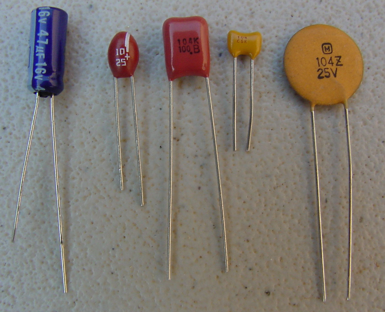 C11
47uF 16V electrolytic, C3 10uF 25V tantalum, C7 0.1uF poly, C9 0.1uF ceramic,
C8 0.1uF disc.
C11
47uF 16V electrolytic, C3 10uF 25V tantalum, C7 0.1uF poly, C9 0.1uF ceramic,
C8 0.1uF disc.
The lead marked with a "+" should be the longer lead,
and represents the anode. The poly, ceramic, and disc capacitors are
direction insensitive. Others should be installed with the longer lead
in the hole marked by a "+" on the circuit board. The tantalum caps have a line indicating
positive (opposite to a diode's marking).
Transistors and Chips
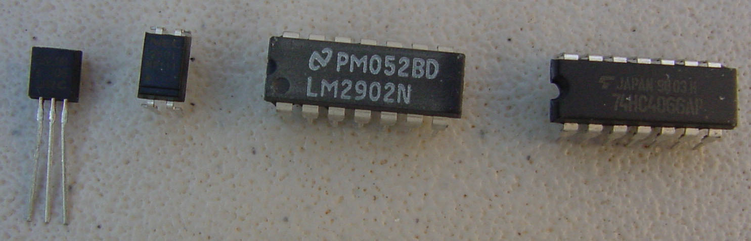 Q1
2N3096, ISO1 PS2501, U2 LM2902, and U3 4066.
Q1
2N3096, ISO1 PS2501, U2 LM2902, and U3 4066.
As is mentioned in "chips.txt", for purposes of the DIY-WB, LM324=LM2902,
CD4066=74HC4066, LM431BIZ=LM431, LM285-1.2=LM385-1.2
For the sake of description, we'll call the end with the semi-circle recess the top. The top-left pin is pin 1. Pin 1 may also be identified by a dot (as is the case with the opto-isolator, ISO1 PS2501). The top is noted on the circuit board by a small rectangle, corresponding to the semi-circle cutout in the chip itself.
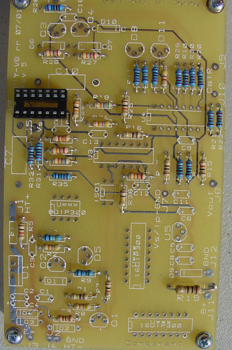
 Drill
1/8" hole at the cross-hairs. Doing this prior to stuffing the board makes
it infinitely easier. Use an old 2x4 as a backing so that the board doesn't
chip as the bit goes through.
Drill
1/8" hole at the cross-hairs. Doing this prior to stuffing the board makes
it infinitely easier. Use an old 2x4 as a backing so that the board doesn't
chip as the bit goes through.
Prepare Work Space
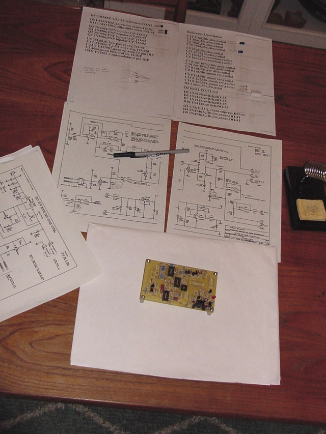 Area
should be well lit, with room for spreading reference materials and parts.
Reference materials might include a printed image of the board, a printed
image of the completed board, and a copy of the schematic (parts a, b, and c). Verify component
labels, values, and orientations on the schematic and check them off as
you install.
Area
should be well lit, with room for spreading reference materials and parts.
Reference materials might include a printed image of the board, a printed
image of the completed board, and a copy of the schematic (parts a, b, and c). Verify component
labels, values, and orientations on the schematic and check them off as
you install.
Solder Resistors
 Are you aware of the basics of good soldering techniques? When you're
ready to begin, start
with resistors. It's a good idea to verify resistance with the voltmeter.
It is also notable that prior to installing other components, there are
only two groups of resistors which connect together to make individual
measurements impossible. When the last resistor is installed in each of
these sets, the reading of those resistors will be altered due to parallelism.
R1, R3, & R8 comprise the first set (they join at B+). The second set
is R11, R14, R31, & R35, & R36 (they connect +4v to VGnd).
Are you aware of the basics of good soldering techniques? When you're
ready to begin, start
with resistors. It's a good idea to verify resistance with the voltmeter.
It is also notable that prior to installing other components, there are
only two groups of resistors which connect together to make individual
measurements impossible. When the last resistor is installed in each of
these sets, the reading of those resistors will be altered due to parallelism.
R1, R3, & R8 comprise the first set (they join at B+). The second set
is R11, R14, R31, & R35, & R36 (they connect +4v to VGnd).
Solder Diodes, Caps, Transistors, Chips, and Wires
 Notice: D6
should be in direct contact with the body of transistor Q3 and D7 should
be in direct contact with Q4. Why? Install transistors Q3 and Q4 before installing the diodes to make this contact easier to create. A touch of heat sink compound may also be used.
Notice: D6
should be in direct contact with the body of transistor Q3 and D7 should
be in direct contact with Q4. Why? Install transistors Q3 and Q4 before installing the diodes to make this contact easier to create. A touch of heat sink compound may also be used.
You may want to use sockets for the mounting of the DIP parts. Radio Shack normally does not stock the high quality sockets which should be used. Nor do they stock the 4 pin variety (as can be noted from this pic). Save the installation of R4 and U1 until the following step.
Mounting in Enclosure
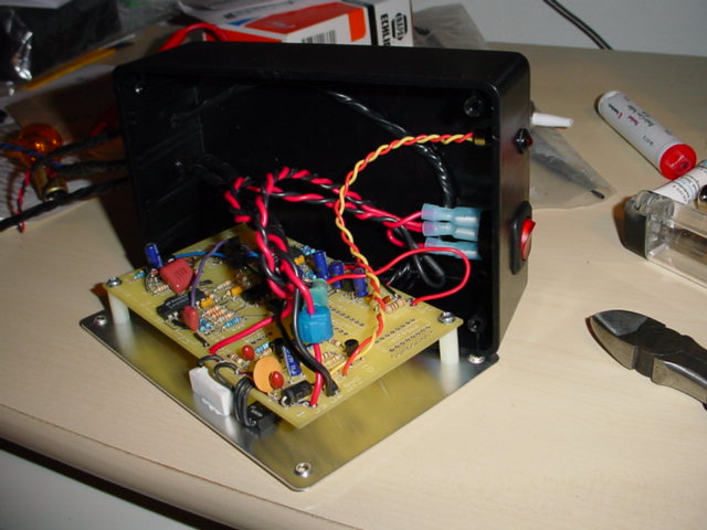 Finished
board is mounted to base plate of project box in a manner that provides
heat sinks for R4 and U1 (photo by Crescent Kao). A white, zinc-based heat transfer glue was used here to mount R4 and U1. Note that the body of transistor U1 will be "live", requiring use of an insulating transistor mounting kit (also available from Radio Shack).
Finished
board is mounted to base plate of project box in a manner that provides
heat sinks for R4 and U1 (photo by Crescent Kao). A white, zinc-based heat transfer glue was used here to mount R4 and U1. Note that the body of transistor U1 will be "live", requiring use of an insulating transistor mounting kit (also available from Radio Shack).